This guide will walk you through how to install the interchangeable tamp.
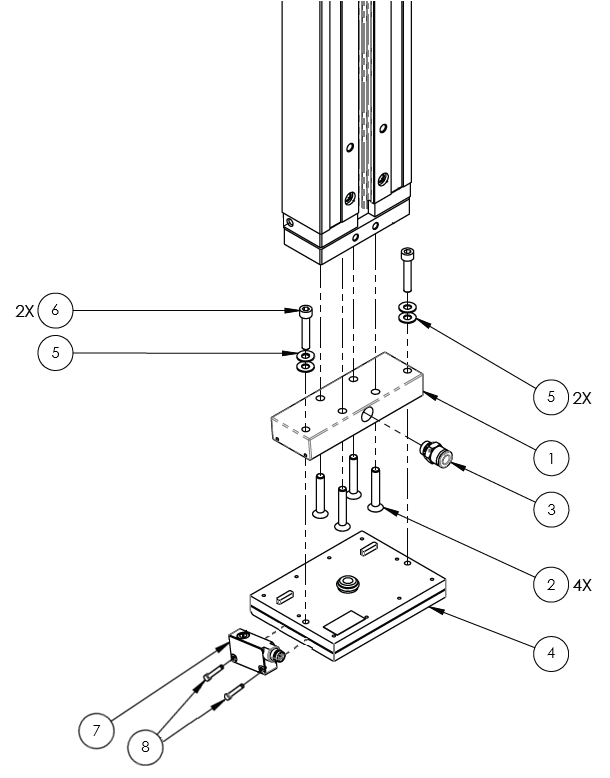
ITEM NO. | PART NUMBER/ID | PART DESCRIPTION |
|---|---|---|
1* | 1010241-02 | MOUNTING BLOCK, CYLINDER TO TAMP HEAD |
2 | 1000436-05-025 | FHSCS, METRIC M5 X 25mm |
3* | 1001604-01 | FITTING, 6mm, MALE CONNECTOR, 1/8 UNI |
4 | 1010252-01-500 | TAMP HEAD ASSY, INTERCHANGEABLE, 1.50" LABEL |
5 | 1002895-01 | WASHER, FLAT, STANDARD, SS, #10 SCREW, .2"ID, .44"OD, .02-.04" THK |
6 | 1000502-10-016 | SHSCS, STANDARD, CZ, 10-32 X 1.00" |
7* | 1010875-02 | SENSOR, PNLCMP, DIFFUSE, 40mm TO 20mm, 24V, NPN, LIGHT DARK SWITCHABLE |
8* | 1007680-03-010 | SHSCS, STANDARD, SS 3-56 X .625" |
NOT PICTURED | 1010252-06-000 | TAMP HEAD ASSEMBLY, INTERCHANGEABLE, 6.00" LABEL |
NOT PICTURED | 1009452-042-01 | CABLE, EIA, INTERCHANGEABLE, TAMP HEAD PRODUCT DETECT |
*Read Before Installation
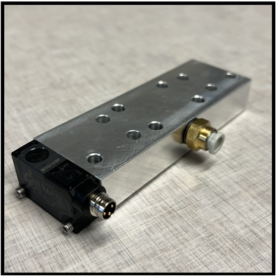
The Mounting Block (1010241-02), Sensor (1010875-02), Air Fitting (1001604-01) and Small Screws (1007680-03-010) will be pre-assembled, so you will not have to assemble these parts (example of assembled mounting block below shown below):
Before installing the new interchangeable tamp, you will need to complete three tasks: turning off the air in the machine, taking the original tamp head off the tamp, and raising the tamp height.
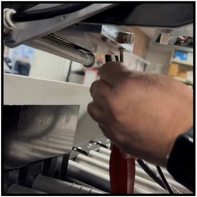
Depressurizing the Machine and Disconnecting the Air Tube
Locate the red air valve on the back of the machine. Turn the valve clock-wise until the valve clicks into place and the hole on the red knob aligns with the hole on the valve. The air in the machine is now turned off. Optionally, operators can now use a lock to lock-out the air valve until installation of the new tamp head is complete.
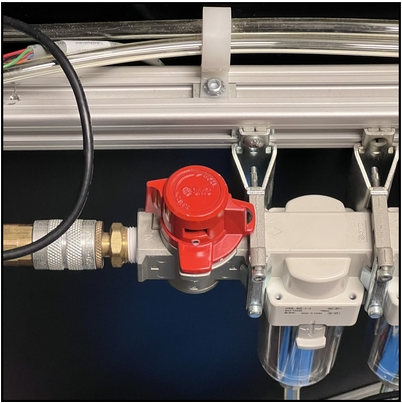
THE VALVE IS ON/PRESSURIZED
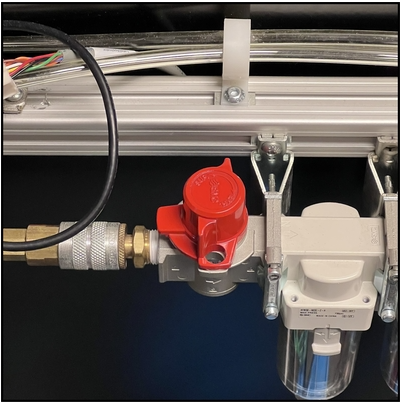
THE VALVE IS OFF/DEPRESSURIZED
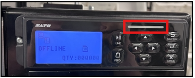
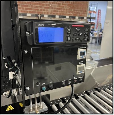
At the front of the machine, locate the printer display. If the display does not specify that the printer is "OFFLINE", press the "LINE" button.
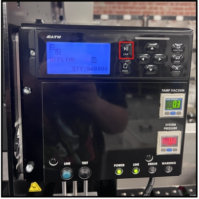
Note
If the light on the printer is off (grey) and the screen says "OFFLINE", then the printer is offline.
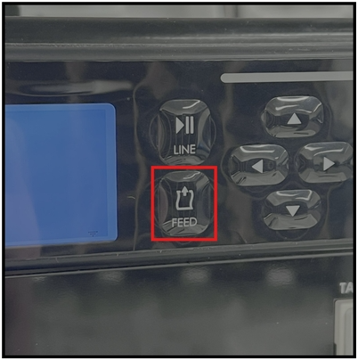
Press the "Feed" button on the printer. This will feed a label through the printer and allow the machine to expel any remaining air in the machine. Once the air in the machine is expelled, the tamp will slowly lower. If the tamp does not lower, gently push the tamp down to make it drop.
Raising the Tamp Height
Open the door of the printer. Unscrew (with your hands) the two caps on the left side of the door.
Tip
When unscrewing the caps from the door of the printer, take extra care to not drop the caps into the transport. Operators may want to consider placing a mail tray or tub on the rollers to prevent the caps from falling into the transport.
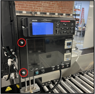
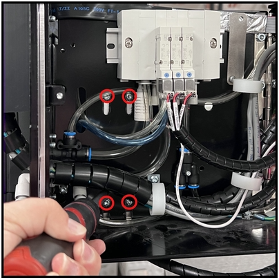
Locate the four screws that attach the tamp to the printer.
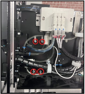
Using a T-25 torx screwdriver, loosen all four screws until the cylinder is easily raised. DO NOT REMOVE THE SCREWS.
Push the cylinder up to the top of the slots.
Holding the cylinder in that position, use the screwdriver to retighten all four screws and secure the cylinder in place.
Removing the Old Tamp Head
Tip
When removing the screws from the old tamp head, take extra to not drop the screws into the transport. Operators may want to consider placing a mail tray or tub on the rollers to prevent screws from falling into the transport.
Unwind the spiral wrap around the air tube and save it for later.
Disconnect the black air tube by pushing the white collar inward (towards the air fitting), and pulling out the tube.
Using a T-25 torx screwdriver, remove the two screws from the BOTTOM of the original tamp head.
Gently remove the original tamp head from the tamp.
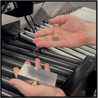
Collect the four flat head screws and the mounting block.
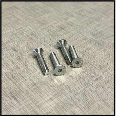
FOUR FLAT-HEAD SCREWS (PART ID 1000436-05-025)
ASSEMBLED MOUNTING BLOCK (CONTAINS PARTS: 1001604-01, 1010241-02, 1010875-02, 1007680-03-010)
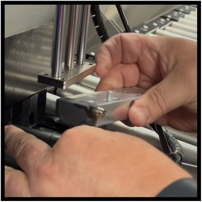
Screw the mounting block into the tamp. Do not tighten the screws until all four screws are inserted.
Collect the tamp head, the two bolts, and the two washers. Place two washers on each bolt to protect the tamp head.
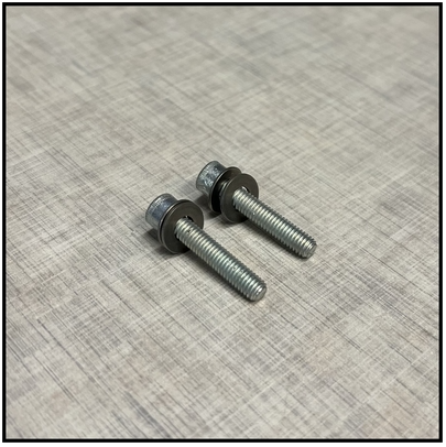
TWO BOLTS, EACH WITH TWO WASHERS (BOLTS PART ID 1000502-10-016, WASHERS PART ID 1002895-01)
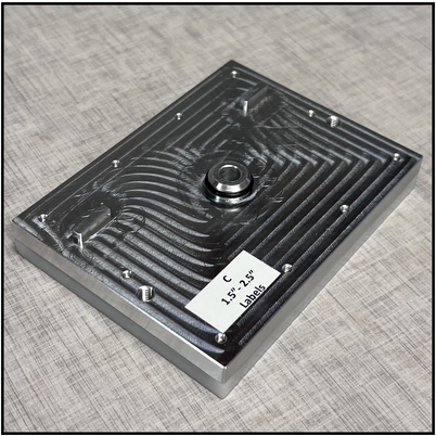
INTERCHANGEABLE TAMP HEAD
Note
The new tamp head being installed may vary from machine to machine, the part IDs for both tamp heads are given below:
1.5" - 2.5" Interchangeable Tamp Head, Part ID: 1010252-01-500
5.5" - 6.5" Interchangeable Tamp Head Assembly, Part ID: 1010252-06-000
The installation process for the new tamp head is the same regardless if the 1.50" tamp head or if the 6.00" tamp head is being used.
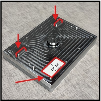
Attach the tamp head to the mounting block.
Note
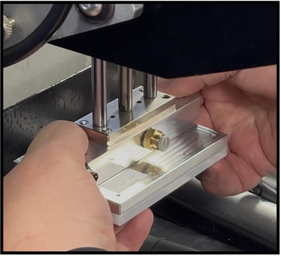
When Installing the new tamp head, line up the back of the mounting block with the notches on the tamp head (as highlighted below). Additionally, make sure that the label on the tamp head is facing you during installation, so that you know the tamp head is being installed correctly.
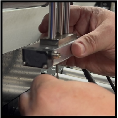
Using two fingers and thumbs on each side of the tamp head, gently push the tamp head up into the mounting block.
Screw a bolt into each hole on either side of the mounting block. Using an allen wrench, snugly tighten the bolts. Take care not to over tighten, as this will strip the threads of the aluminum mounting block.
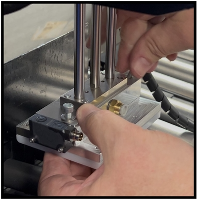
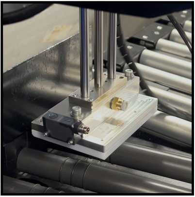
THE IMAGE ABOVE SHOWS WHAT THE TAMP WILL LOOK LIKE AFTER THE NEW TAMP HEAD IS INSTALLED.
Important
The new tamp head is now installed. However, the air tube needs to be reconnected and the cable connecting the sensor to the printer's board needs to be installed.
Reconnecting the Air Tube and Installing the Interchangeable Tamp Head Cable:
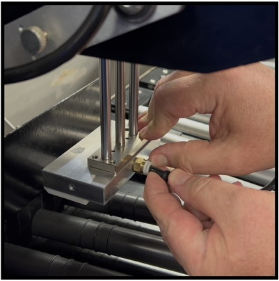
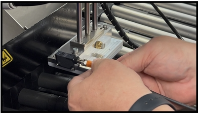
Plug the XLR end of the cable into the XLR receptor on the sensor.
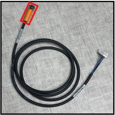
CABLE, ORANGE XLR CONNECTOR END (PART ID 1009452-042-01)
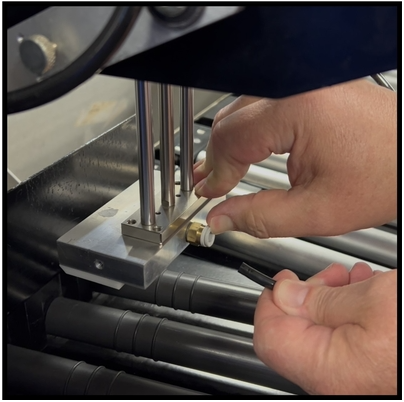
Firmly push the air tube into the air fitting until it stops.
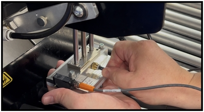
Important
Before reinstalling the air tube, verify that the tube is straight and not damaged to prevent air leaks. If the tube is damaged, cut off the damaged part of the tube.
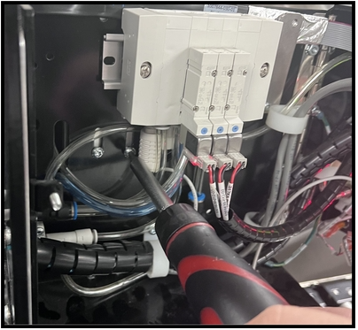
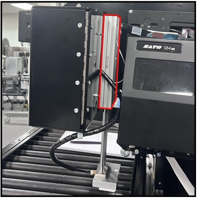
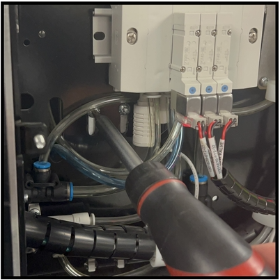
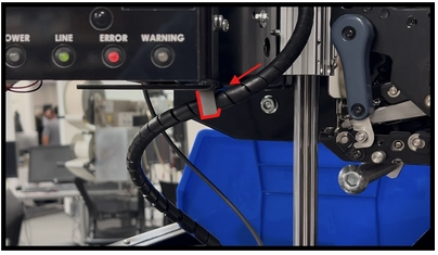
On the back of the printer, locate the opening where the air tube enters the printer next to the air cylinder. Route the white connector into the printer through this opening.
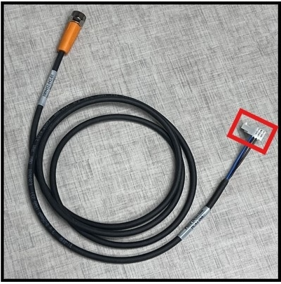
CABLE, WHITE CONNECTOR END (PART ID 1009452-042-01)
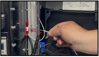
THE IMAGE ABOVE SHOWS DEMONSTRATES WHERE THE WHITE CONNECTOR END SHOULD BE ROUTED THROUGH.
Inside the printer, you should see the white connector coming through the vertical opening in the back of the printer. Gently pull the cable through the vertical opening, tucking it behind the hoses in the printer. Direct the cable up through the white wire holders over to the Applicator Control Board.
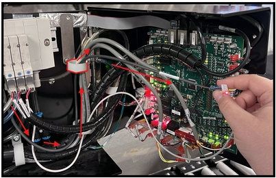
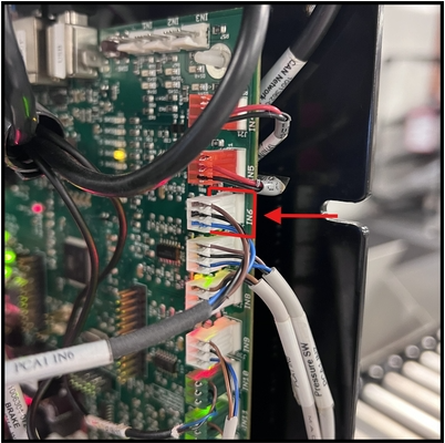
Carefully plug the cable into the IN6 on the board (it will be labeled).
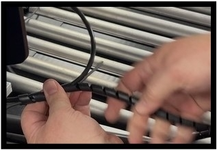
Wind the spiral wrap around the tube and cable until the bundle is fully covered. Once you're done wrapping the cable and tube, hook the bundle onto the white wire organizer.
Close the door of the printer and screw the caps back in to secure the control panel. The installation of the interchangeable tamp is now complete.
Was this article helpful?
That’s Great!
Thank you for your feedback
Sorry! We couldn't be helpful
Thank you for your feedback
Feedback sent
We appreciate your effort and will try to fix the article