The Dimensioner is an add-on product, designed to seamlessly integrate into a user’s existing machine or processing system. This guide walks users through the process of installing a Dimensioner onto an EZ-Flats machine.
- Parts Included in Kit
- Installing the Dimensioner
- Creating Dimensioner-Compatible Job Profiles
- Processing Mail with the Dimensioner
Part | Part ID/Description | Quantity |
|---|---|---|
RealSense Dimensioner Camera | 1013913-01 D415 REALSENSE DIMENSIONER | 1 |
Camera Mount | 1014073-01 CAMERA MOUNT, REALSENSE | 1 |
Right Angle Adapter | 1013943-01 USB C 3.2 PLUG TO USB C3.2 RECEPTICAL, GEN 1 | 1 |
Button Head Socket Cap Screws | 1000353-10-008 BHSCS, STANDARD, CZ | 2 |
Socket Head Cap Screws | 1000612-03-008 SHSCS, METRIC, CZ | 2 |
USB 3.0 Cable | 1013943-01 USB C 3.2 PLUG to USB 3.2 RECEPTICAL, GEN 1 | 1 |
Camera Stand Channel Cover | 1000278-01 CAMERA STAND CHANNEL COVER | 1 |
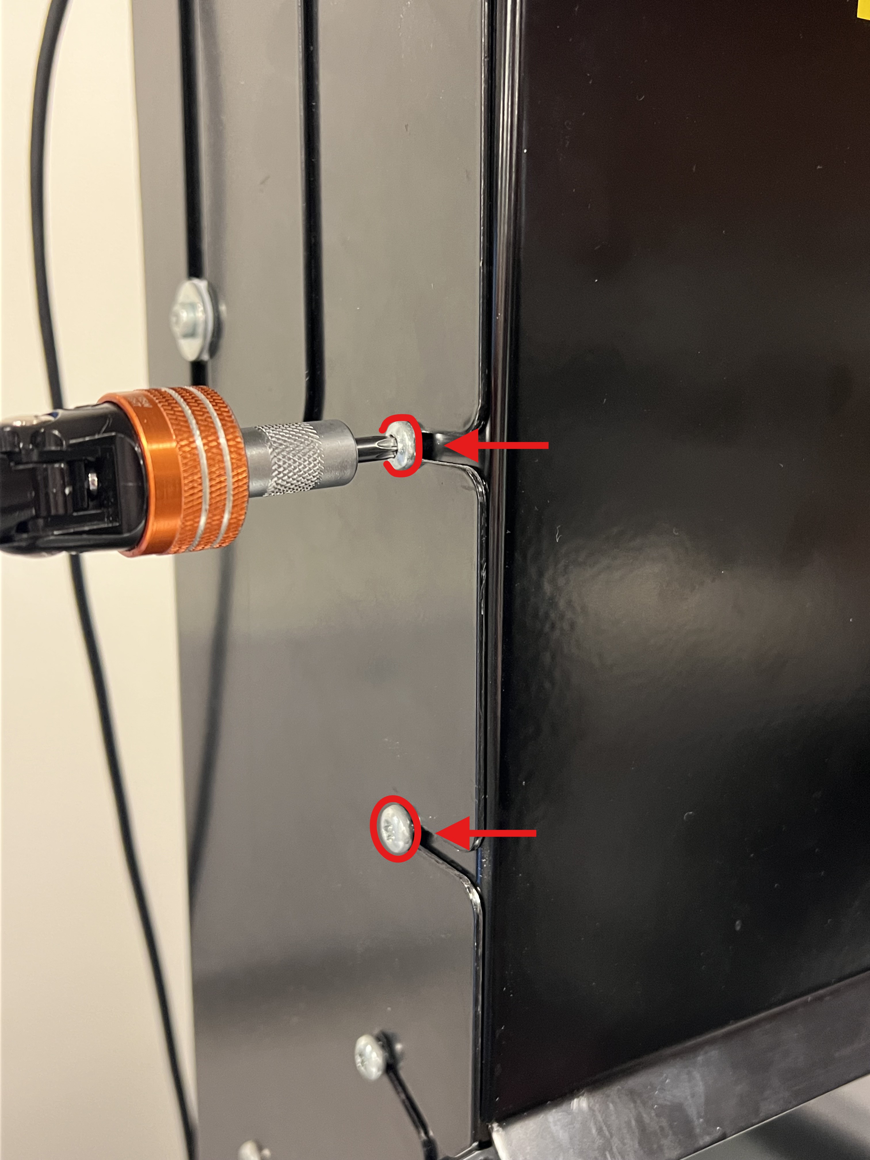
Using a screwdriver, loosen the top two screws on each side of the channel cover, until the cover can slide forward.
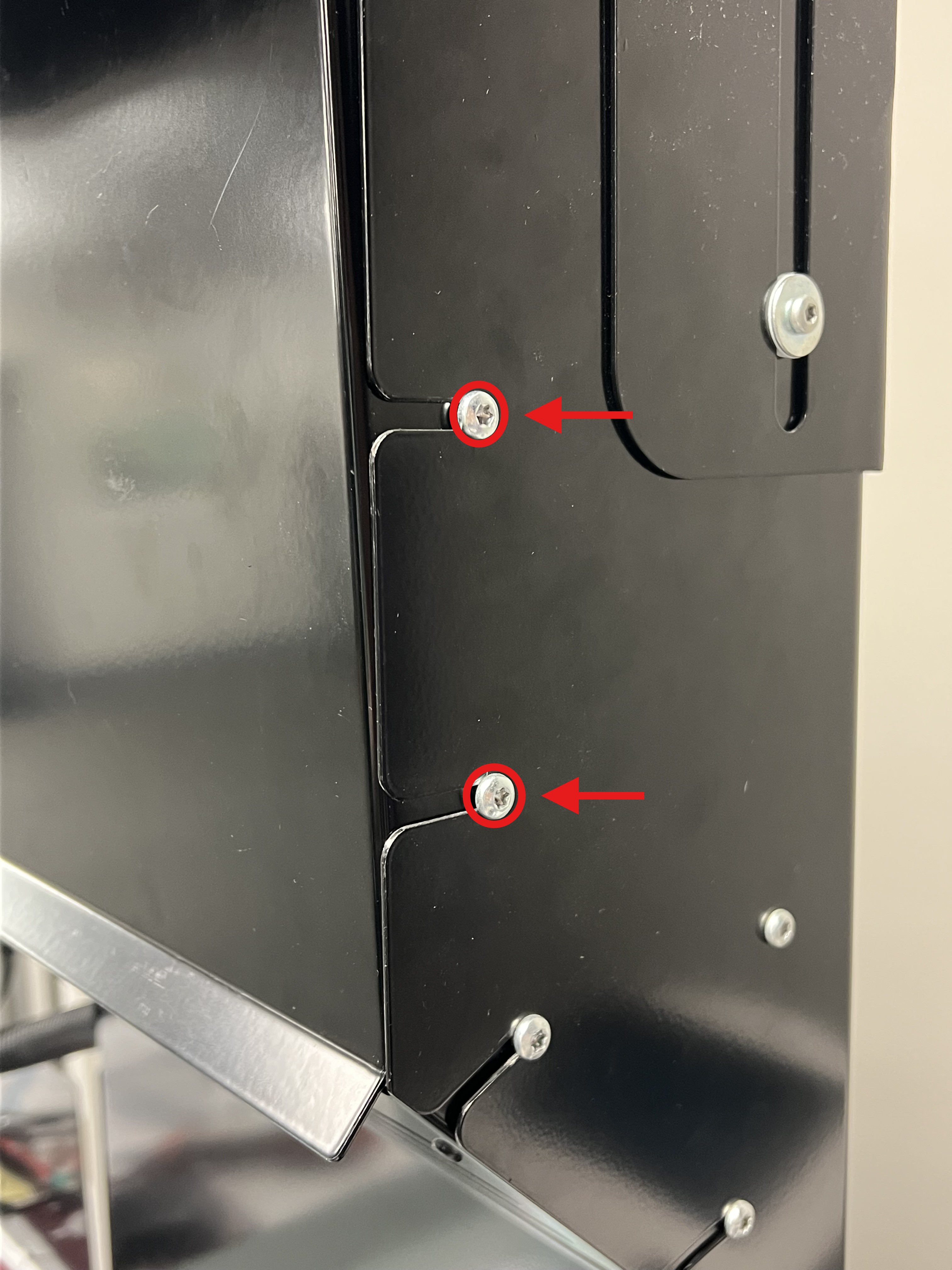
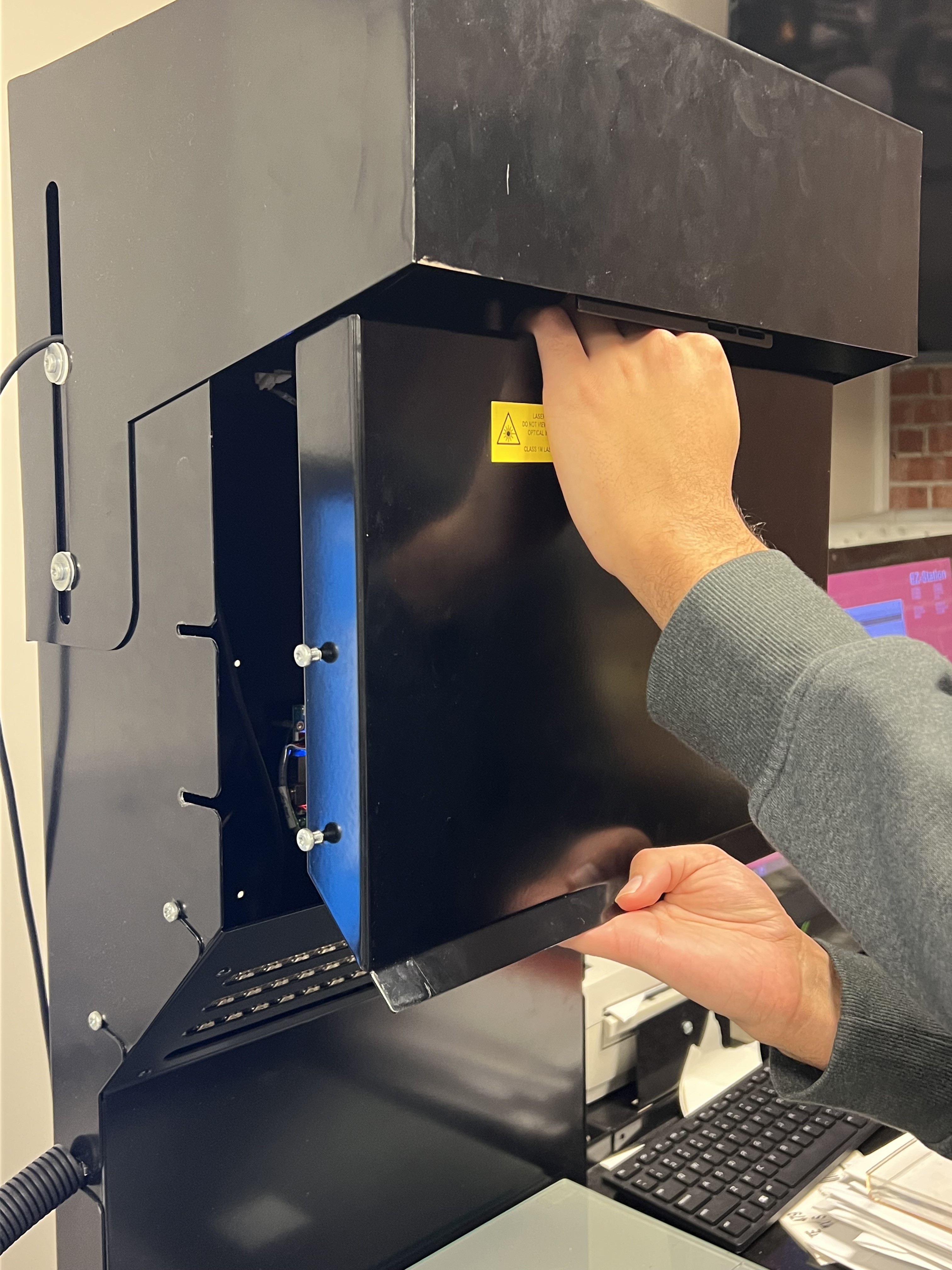
Gently pull the channel cover off of the machine and set the cover aside.
Take the USB 3.0 cable (1013943-01) out of the kit.
Feed the cable through the channel opening and out of the bottom-right side of the channel.
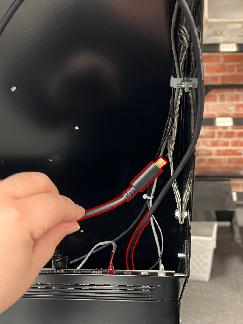
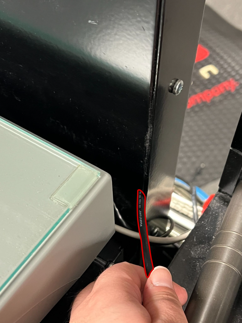
Route the cable under the rollers and out near the Workstation computer at the back of the machine.
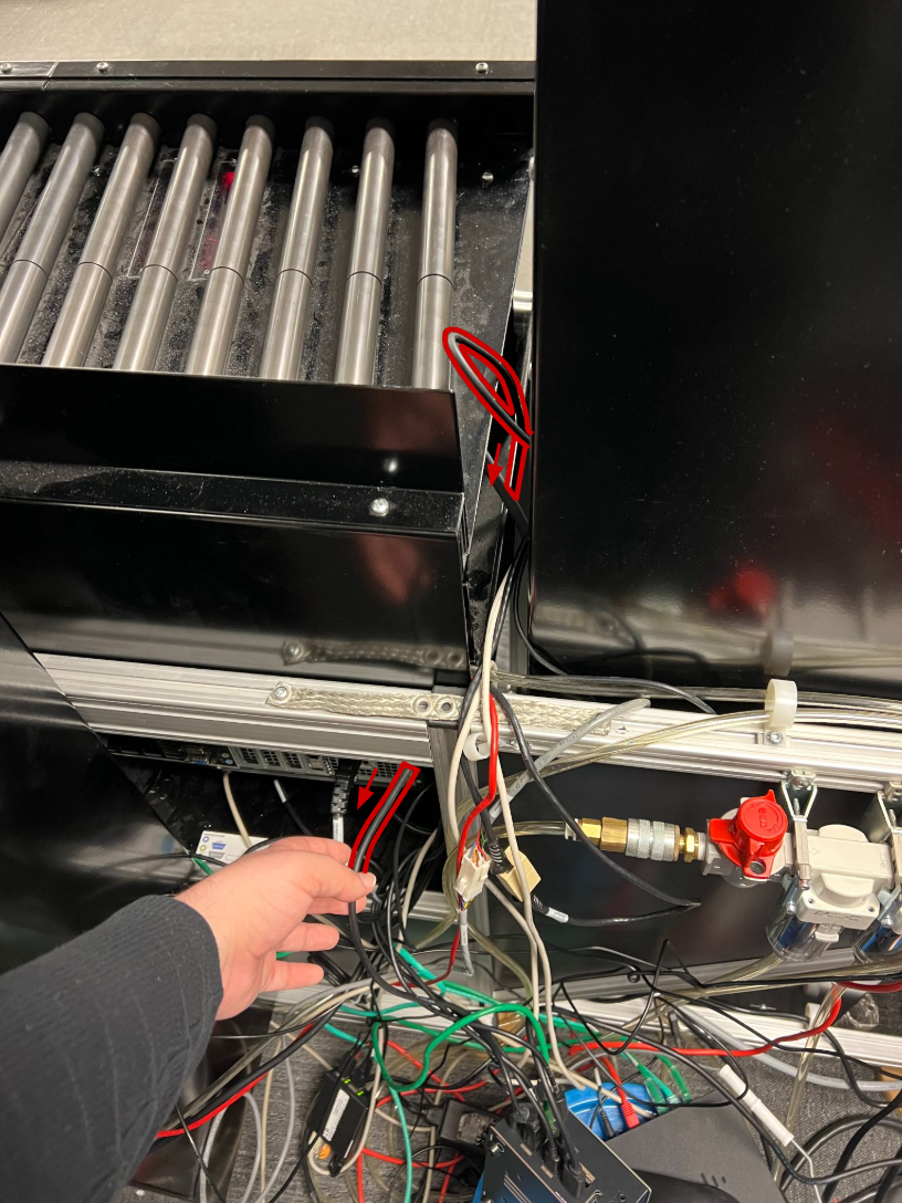
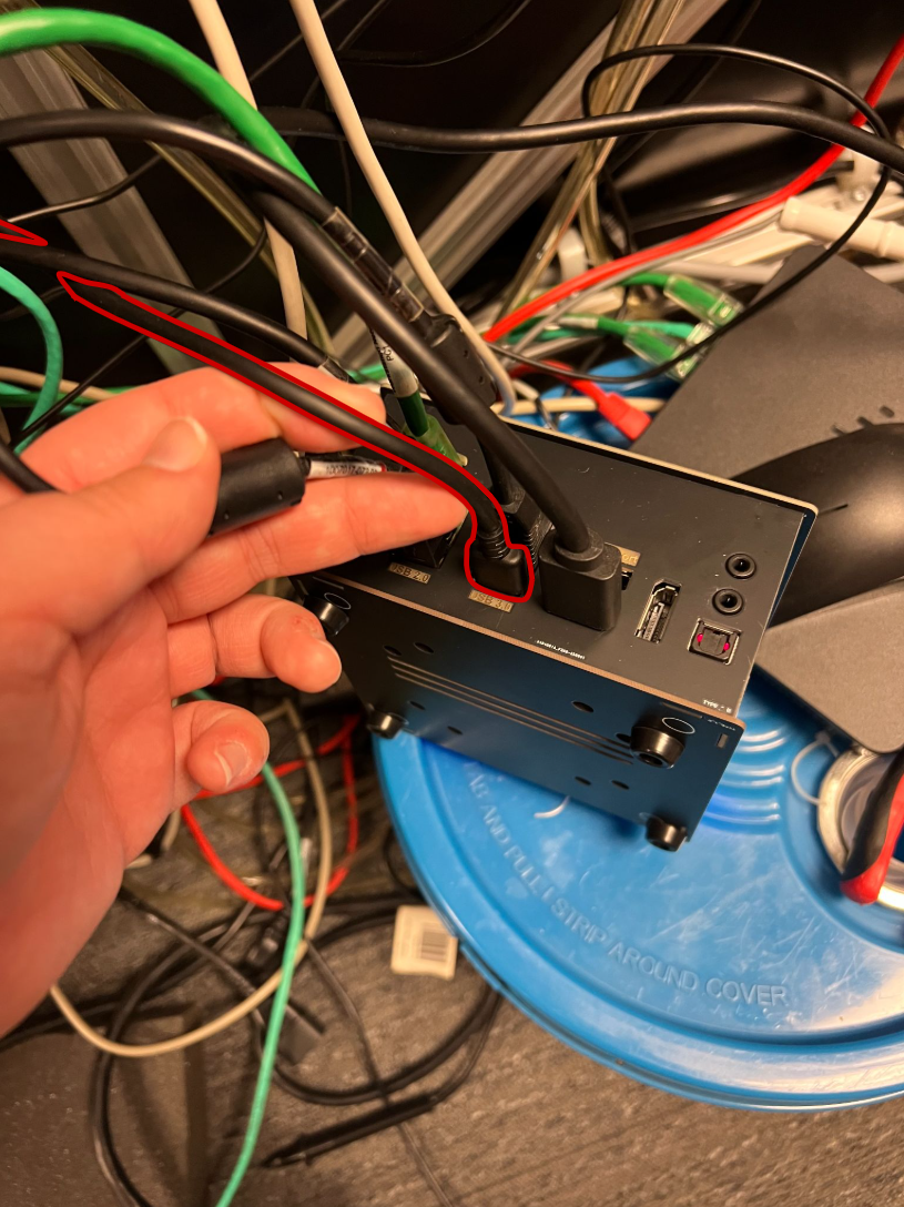
Plug the cable into a USB 3.0 port on the machine USB hub.
- Use zip ties or twist ties to secure the USB 3.0 cable to the other cables in the channel.
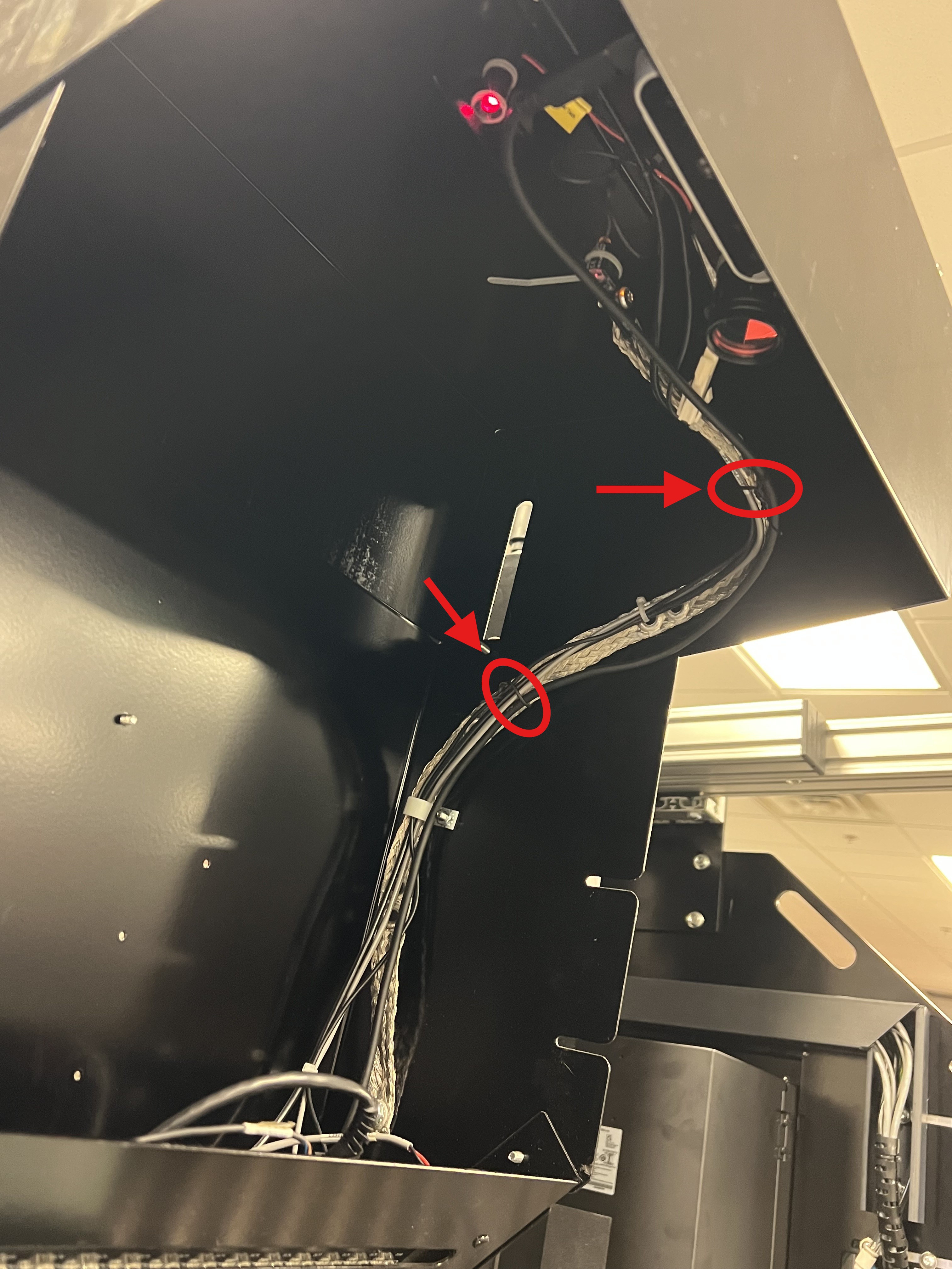
This will prevent the cable from blocking the red laser sensor during processing.
Take the Dimensioner camera (1013913-01) and the Right Angle adapter (1013943-01) out of the kit.
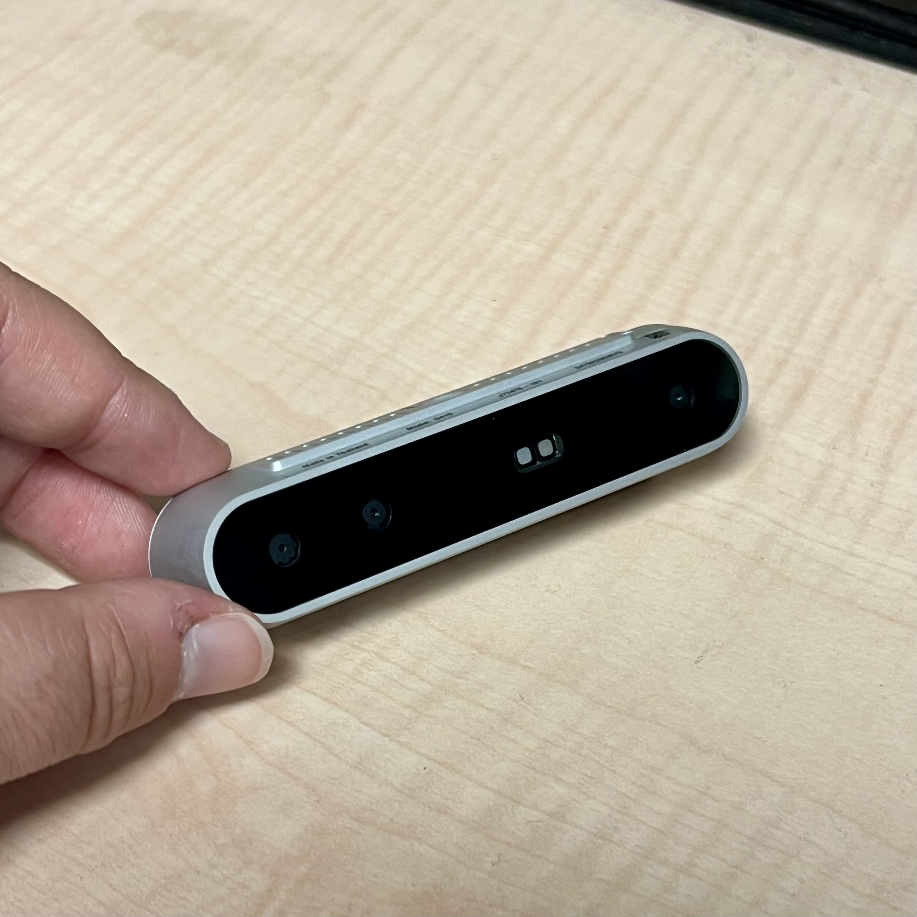
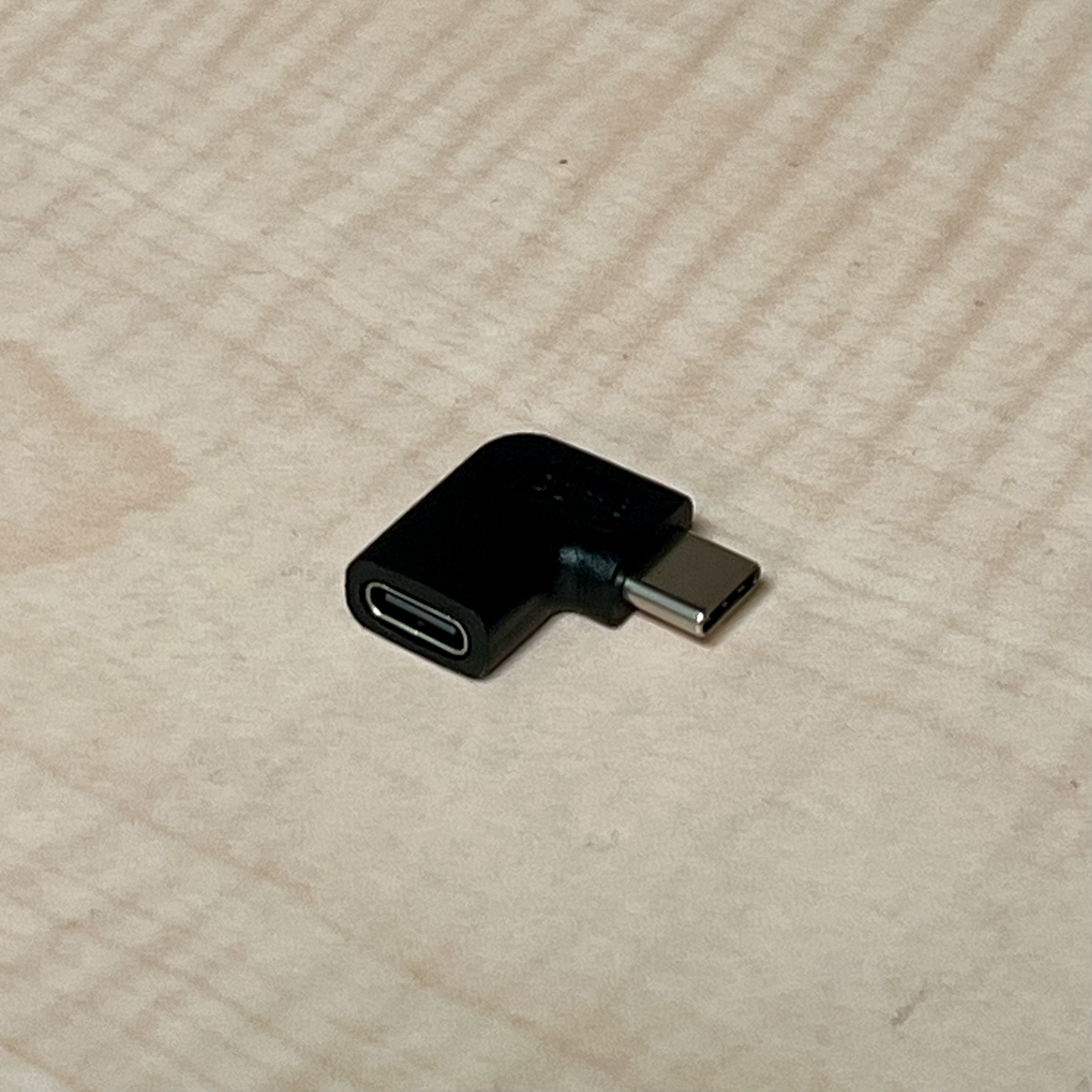
- Plug the adapter into the USB 3.0 port on the camera.
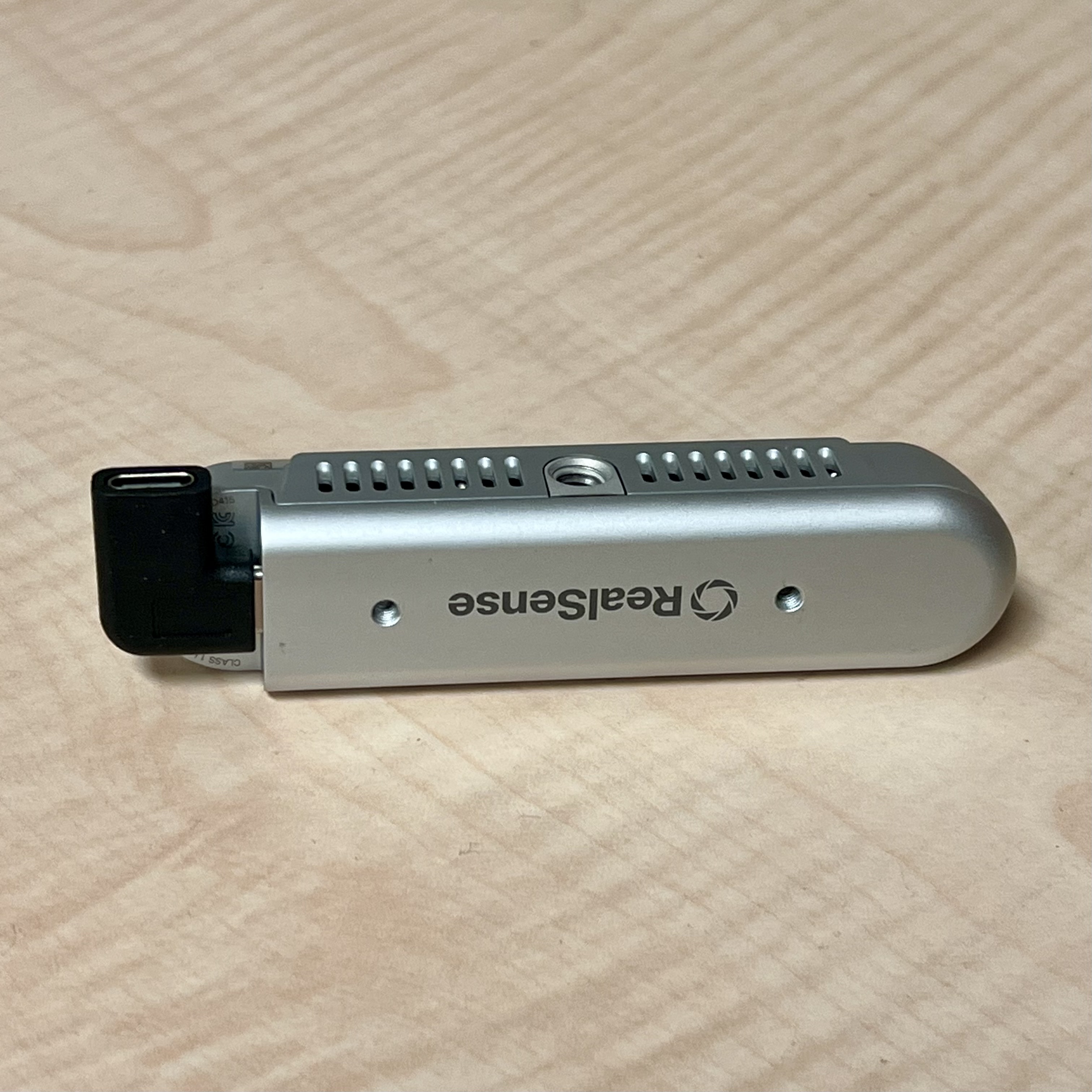
The adapter should face the same direction as the threaded hole on the top of the camera.
Take the Camera mount (1014073-01) and the two Socket Head Cap Screws (1000612-03-008) out of the kit.
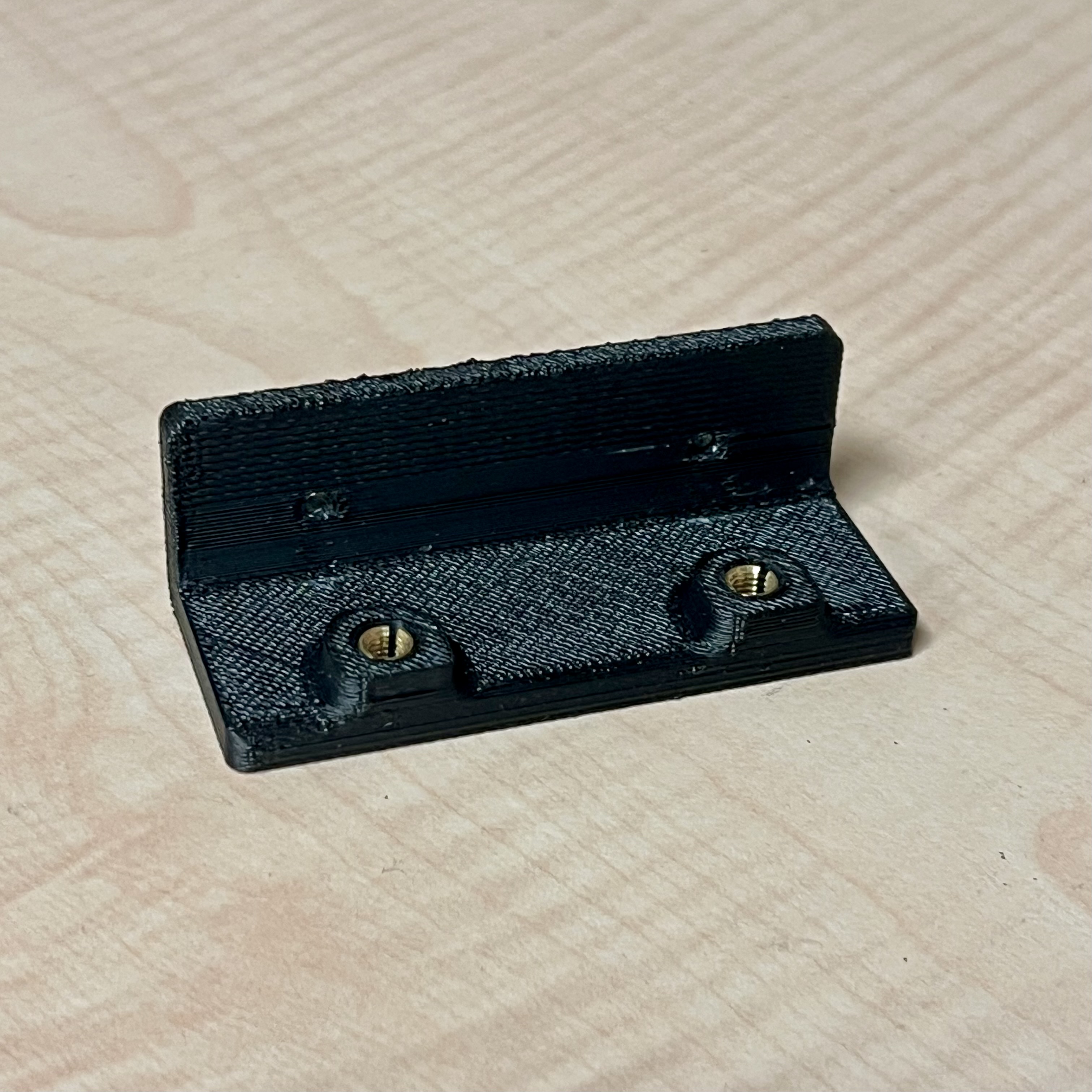
Align the two small threaded holes on the back of the camera with the two small holes on the Camera mount.
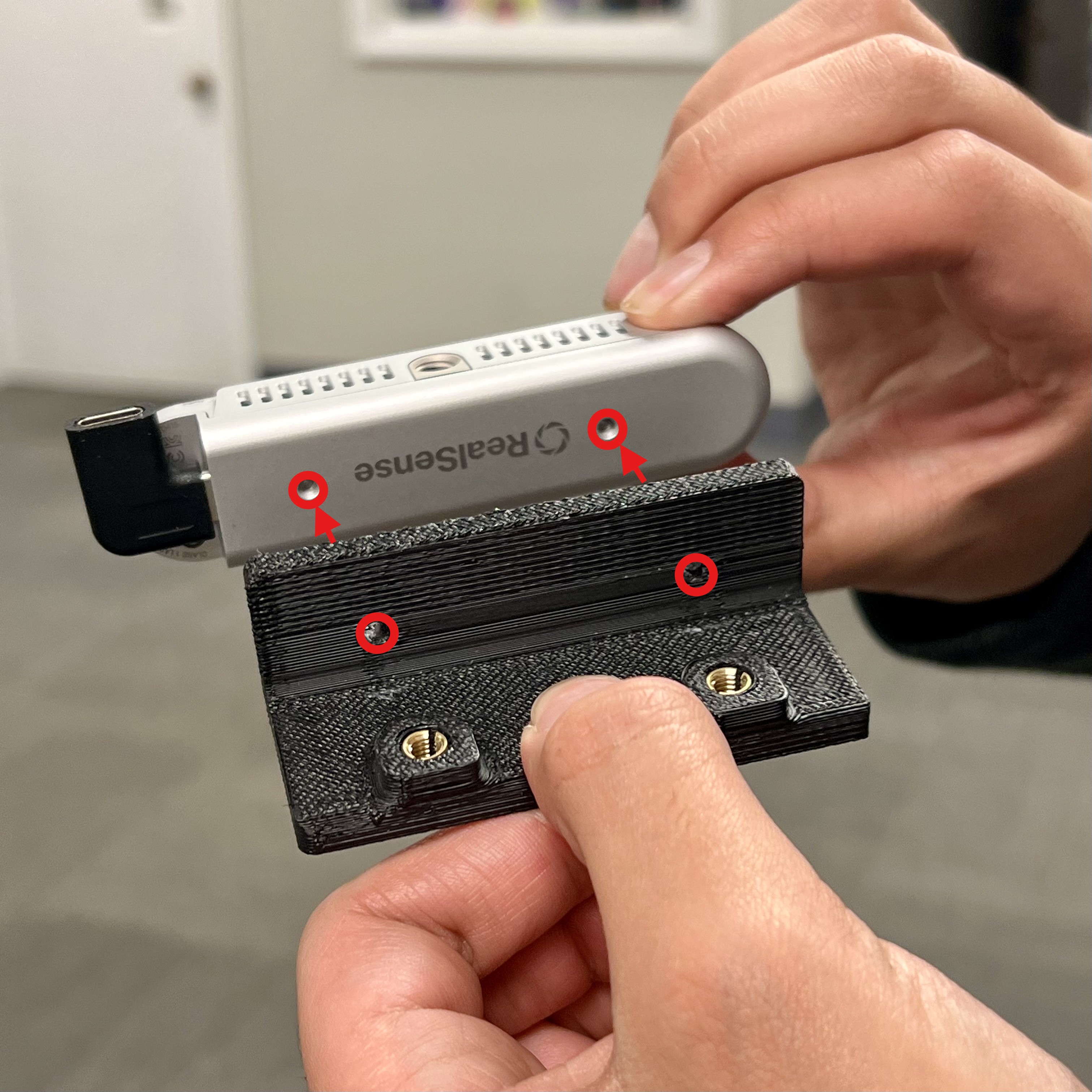
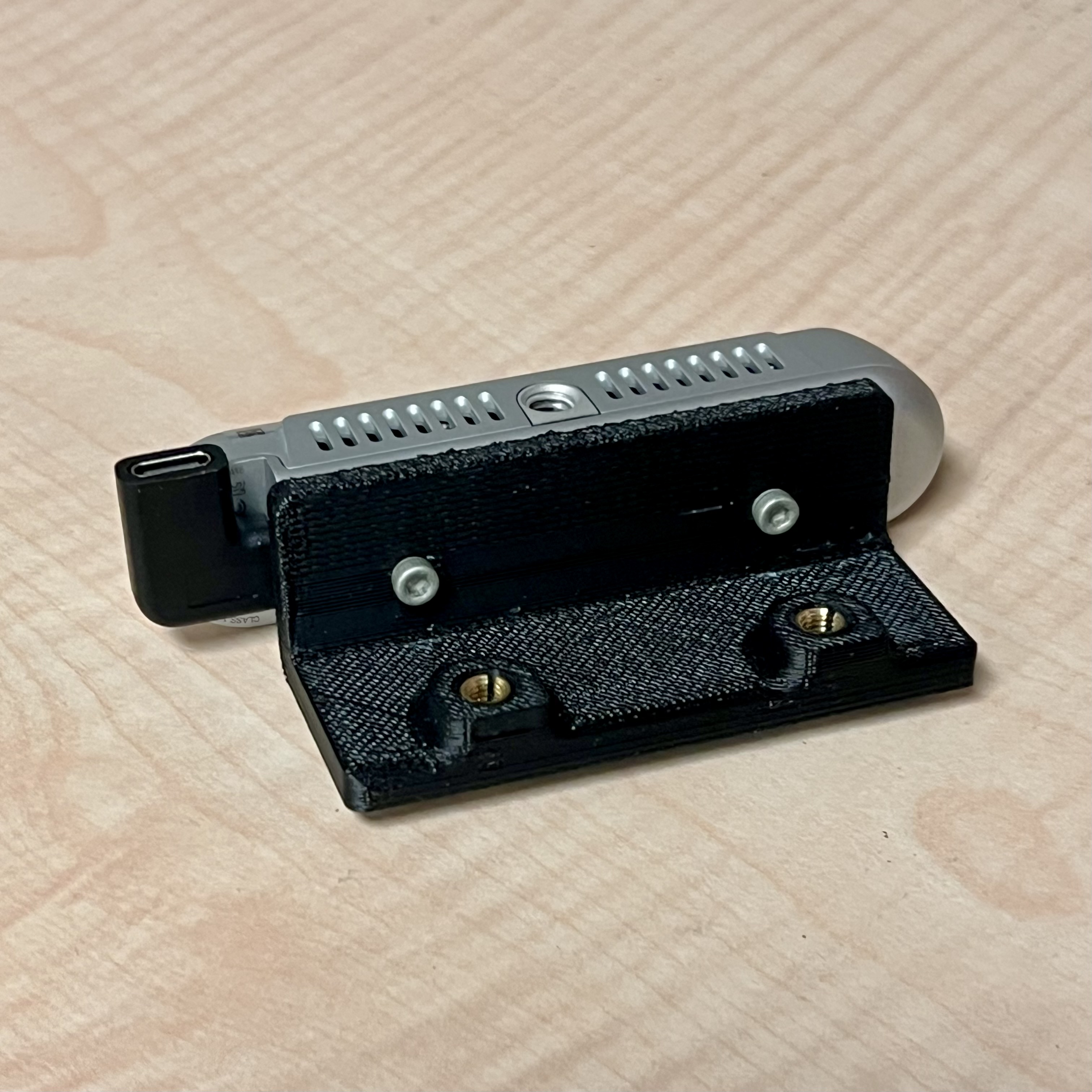
Insert and hand-tighten the screws into the holes, connecting the mount to the camera.
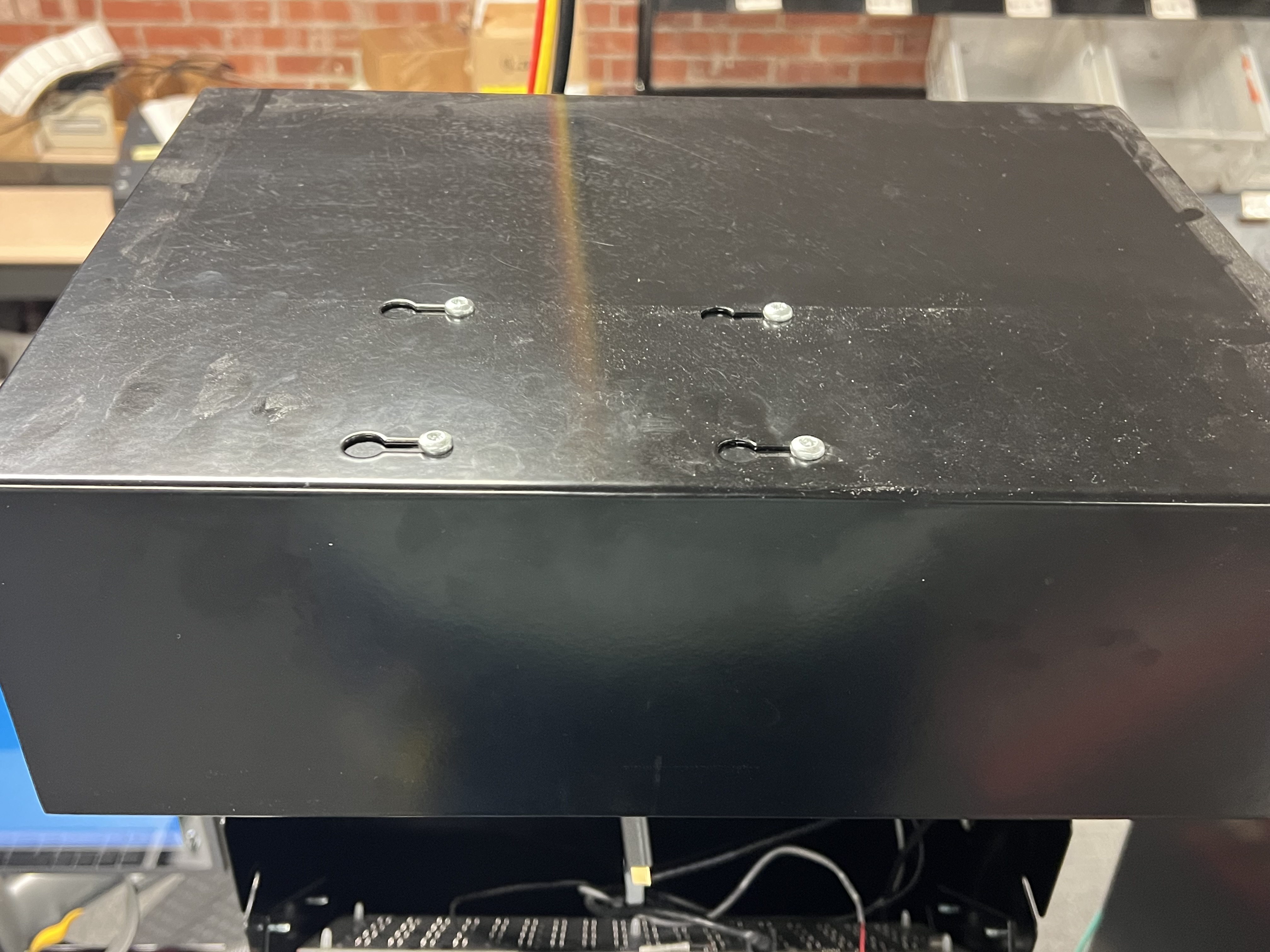
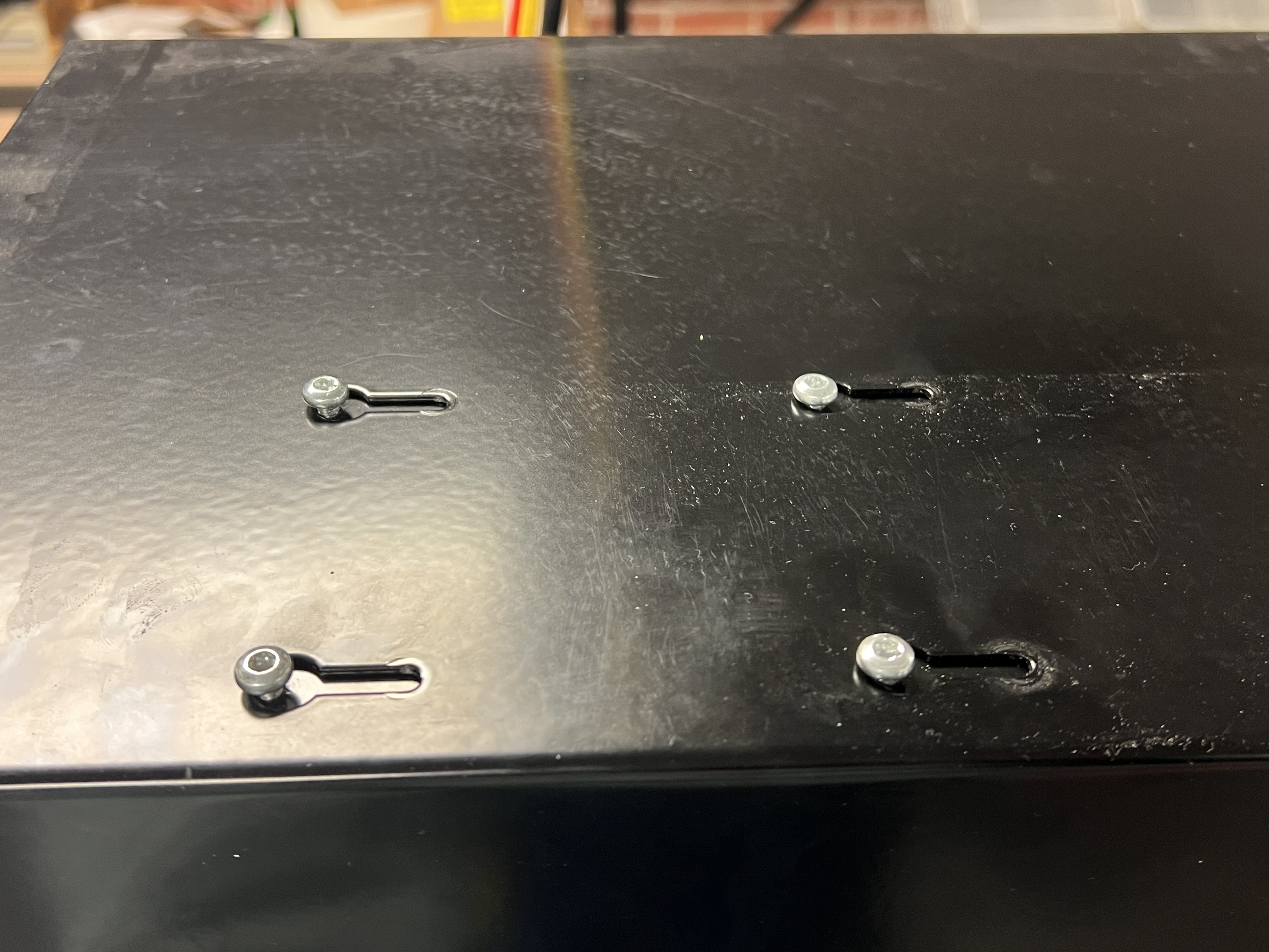
Attached to the top of the channel is the unit on which the machine's camera is mounted. On the top of the machine, locate the four screws connecting the unit to the machine.
Users may need to use a stool to access the top of the machine.
Use one hand to loosen the screws with a screwdriver and the other hand to hold the unit and prevent the unit from falling.
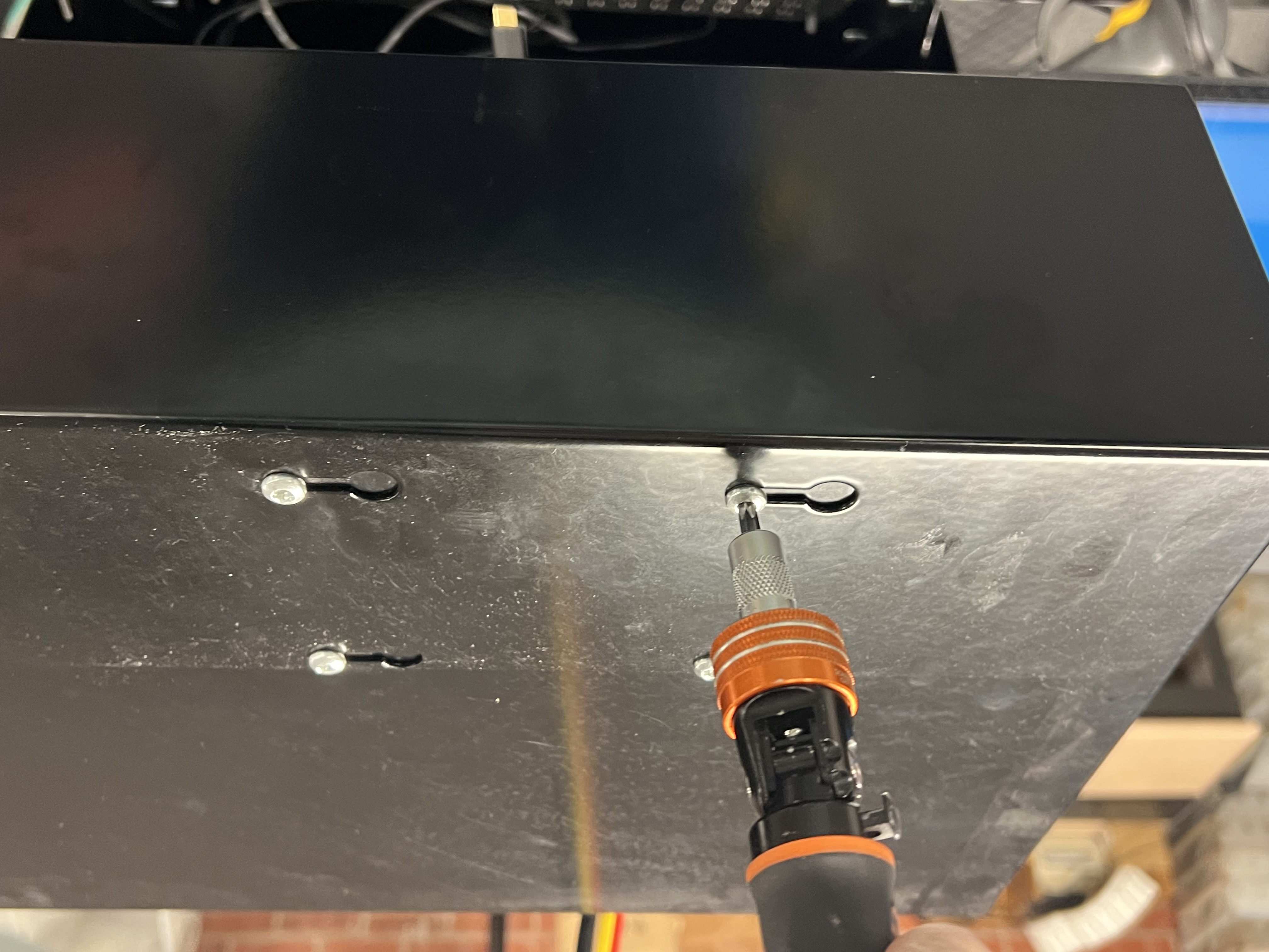
- Gently slide the unit all the way to left and pull the unit away from the top of the machine.
- Users can temporarily rest the unit of the weight scale below.
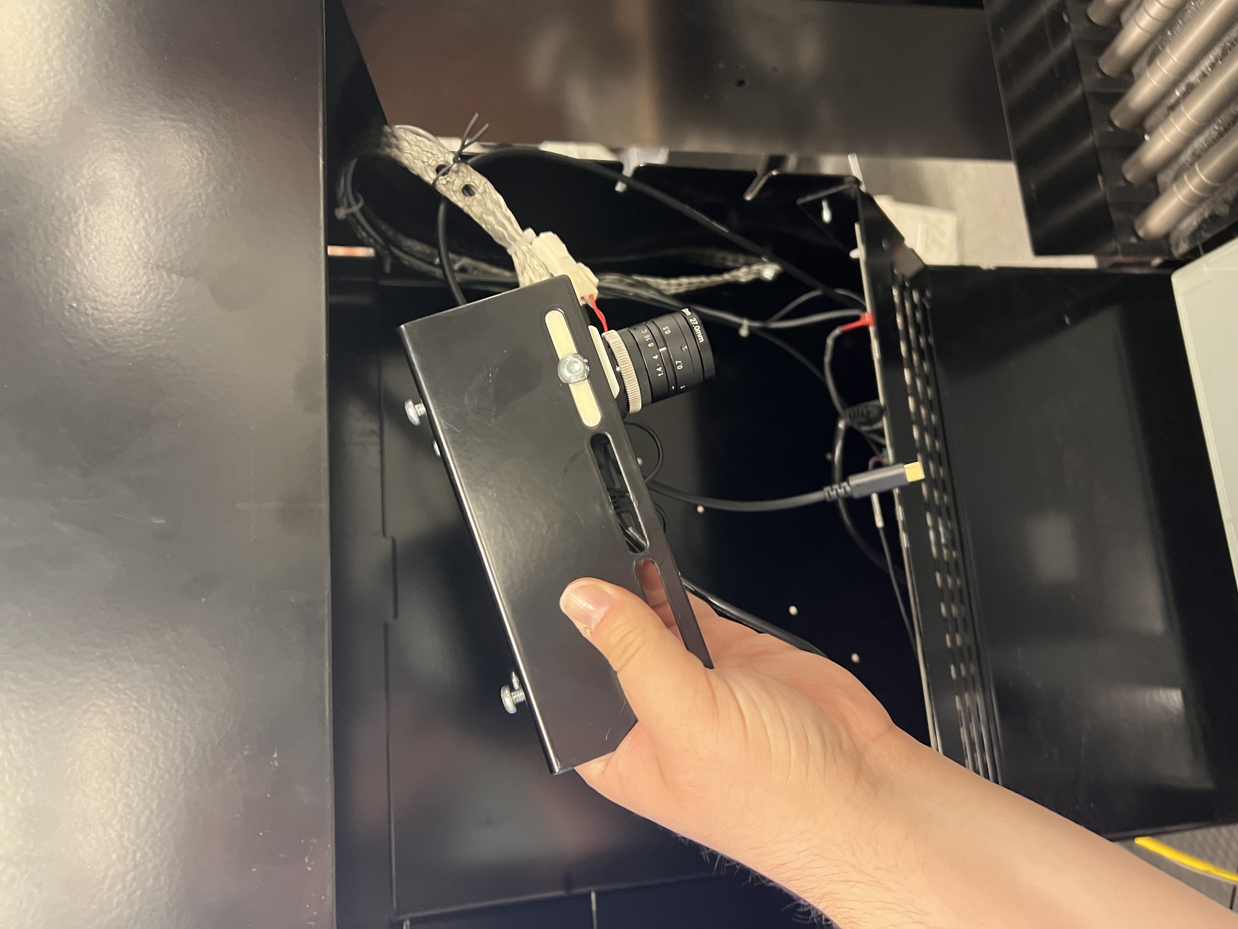
Take the two Button Head Socket Cap Screws (1000353-10-008) from the kit and pick up the camera/mount.
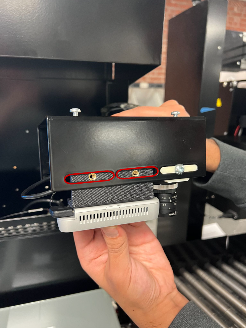
Align the threaded brass holes on the Camera mount with the slots on the unit (see example picture below).
Insert the screws into the holes, adjust the camera/mount position so that the screws are close to/in the middle of the slots.
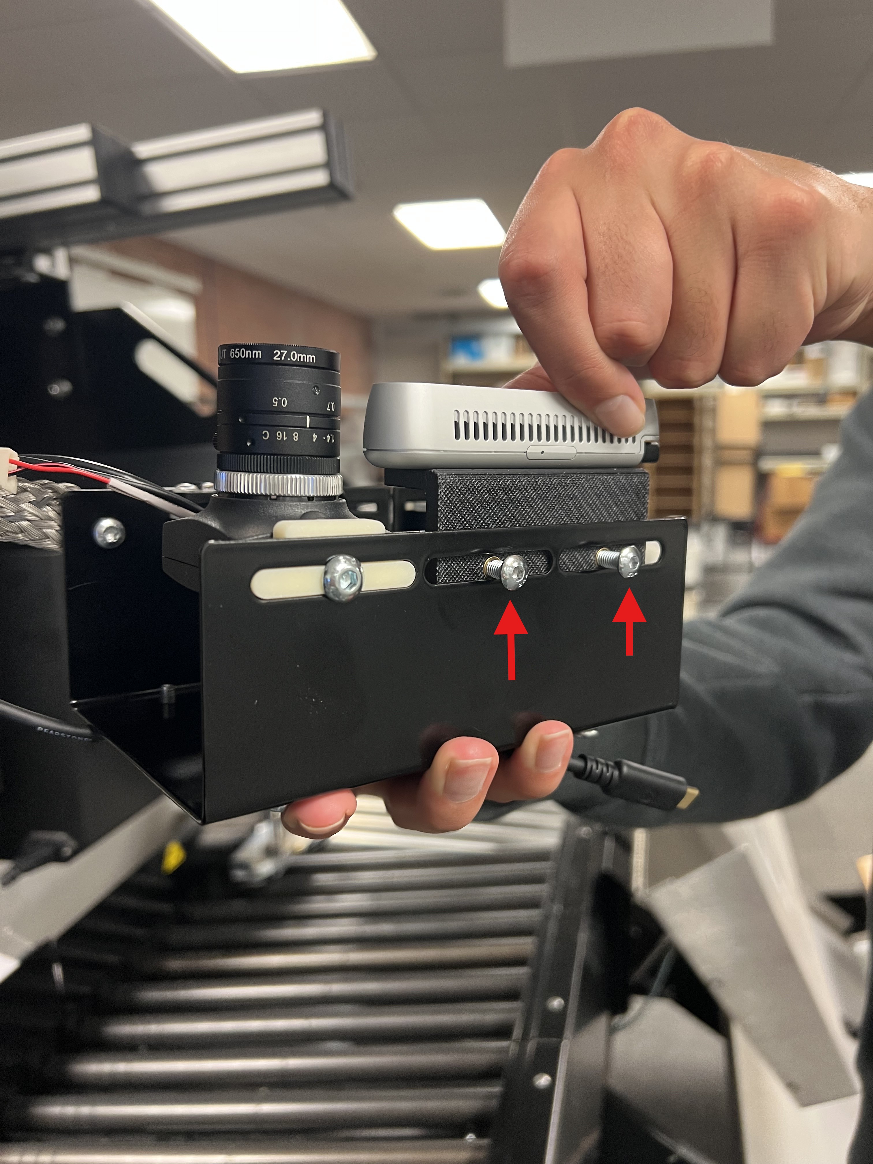
- Tighten the screws, securing the camera/mount to the unit.
After attaching the Dimensioner camera to the unit, users will reattach the unit to the top of the channel.
Locate the four slots at the top of the channel.
Insert the screws into the slots and gently slide the unit all the way to the right.
Use one hand to tighten the screws with a screwdriver and the other hand to hold the unit and prevent the unit from falling.
- Plug the USB 3.0 cable into the Right Angle adapter attached to the Dimensioner camera.
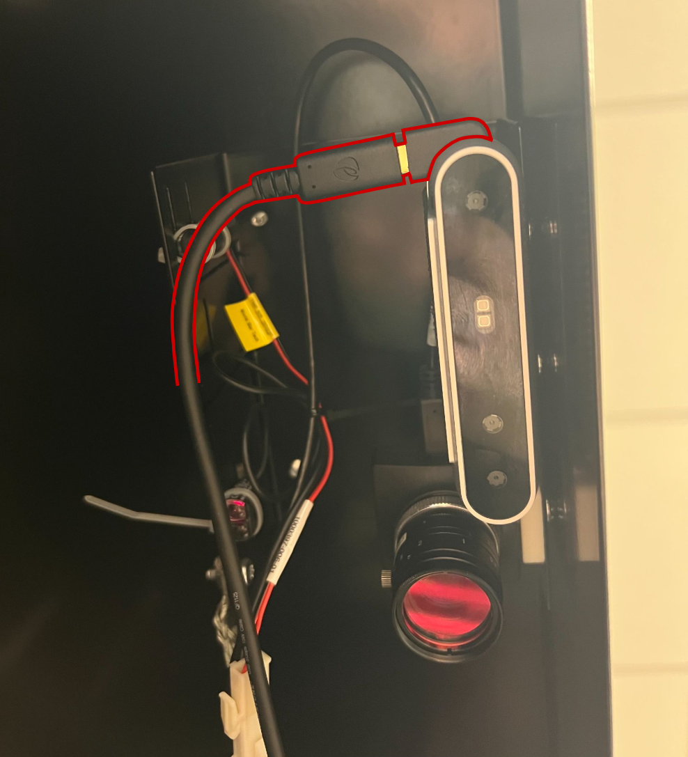
Make sure that the cable is not blocking the red laser sensor. When the Dimensioner camera is plugged in, the machine computer may show an on-screen notification with an audio cue.
Take the new Camera Stand Channel cover (1000278-01) out of the kit.
Slide the new cover into the location of the original channel cover.
Using a screwdriver, tighten the top two screws on each side of the channel cover, securing the cover to the machine.

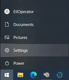
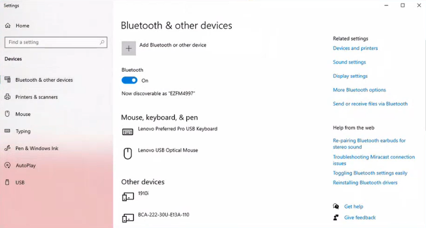

After installing the Dimensioner, users will need to create Dimensioner-compatible job profiles to use when running a job with the Dimensioner. Users can create as many compatible job profiles as needed.
On the computer desktop, click on the Console shortcut.

The Console will open.
In the Console, select the Job Profile Editor from the "Editors" list.
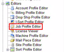
The user will be directed to the Editor.
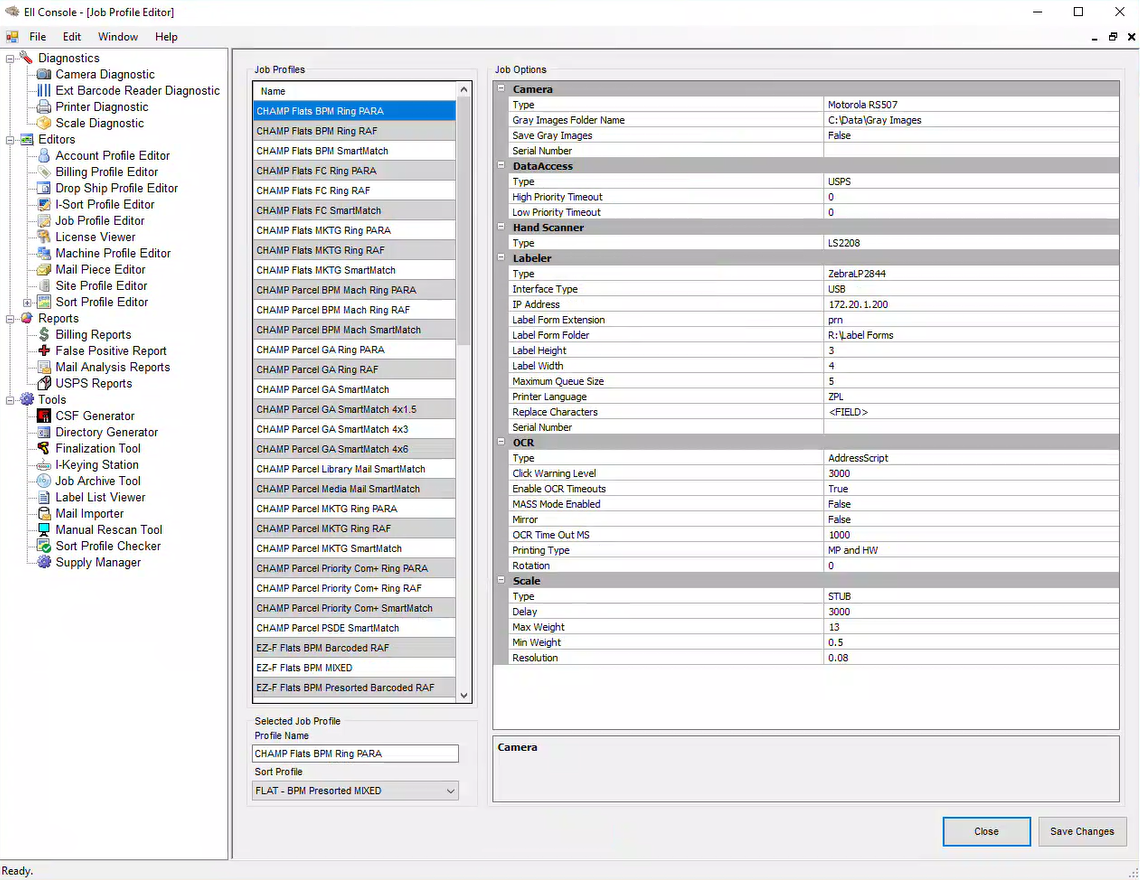
- In the Job Profile Editor, right-click on a job profile to copy from the "Job Profiles" list.
A pop-up menu will open.
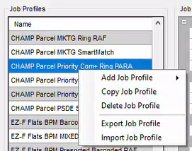
- Select the "Copy Job Profile" option.
A new profile will be generated and added to the bottom of the "Job Profiles" list.
Select the newly created job profile, give the job profile a new name in the "Select Job Profile" section.
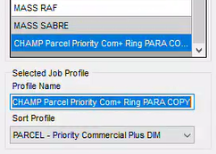
The name should indicate that this profile is a Dimensioner-compatible job profile, something like "[Job Profile Name] - DIM" or "[Job Profile Name] + DIM".
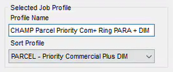
Click on the "Save Changes" button to save the job profile.

Reselect the job profile from the list.
In the "Job Options" section on the right, locate the "Scale" component in the list.

- Click on the drop-down list for the component's "Type" setting and select the "MTPS30" option from the list.

The settings for the component will change slightly. These settings do not need to be edited.
Right-click anywhere on the "Job Options" section.
A pop-up menu will open.
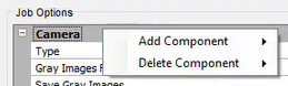
- Select the "Add Component" option.
A second pop-up menu will appear.
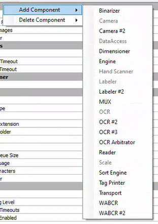
- Select the "Dimensioner" component.
The "Dimensioner" component will be added to the bottom of the "Job Options" section.

Scroll down to the "Dimensioner" component.
Click on the drop-down list for the component's "Type" setting and select the "RealSense Dimensioner" option from the list.

The settings for the component will change slightly. These settings do not need to be edited.
Click on the "Save Changes" button to save the profile.
On the computer desktop, click on the EZ Helm shortcut.

The EZ Helm will open.
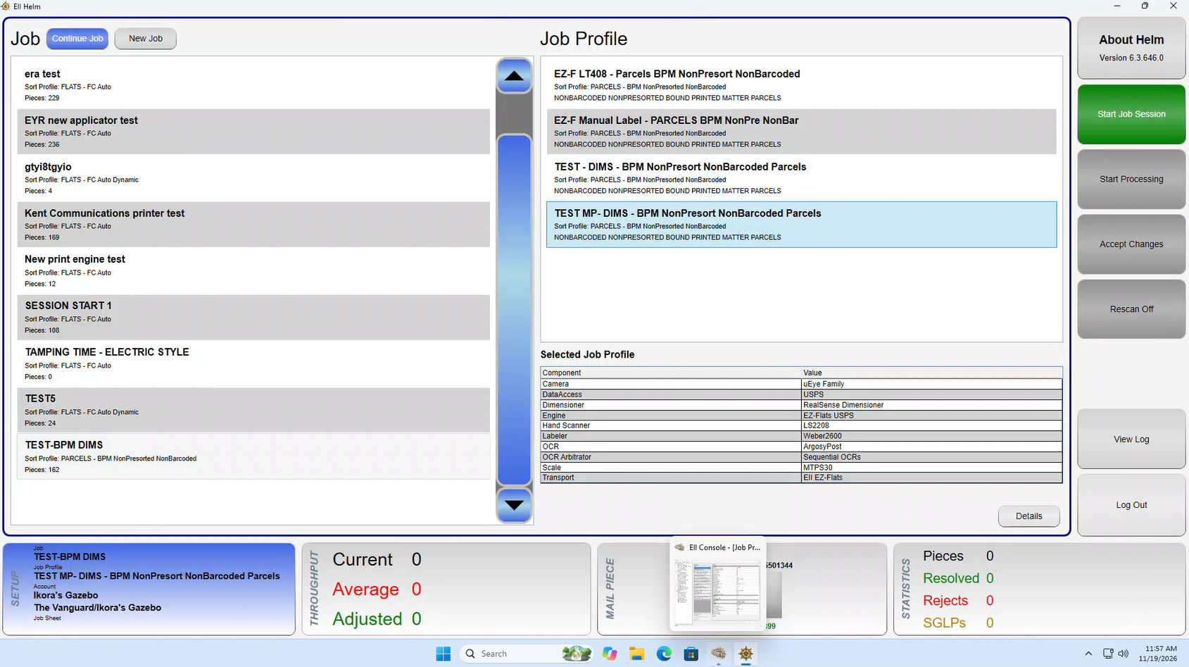
In the EZ Helm, continue or create a new job in the "Job" section.
Select a Dimensioner-compatible job profile in the "Job Profile" section.
Click on the green "Start Job Session" button.

The machine will verify its connection to all machine components and then direct the operator to the "Account"/"Department" page.
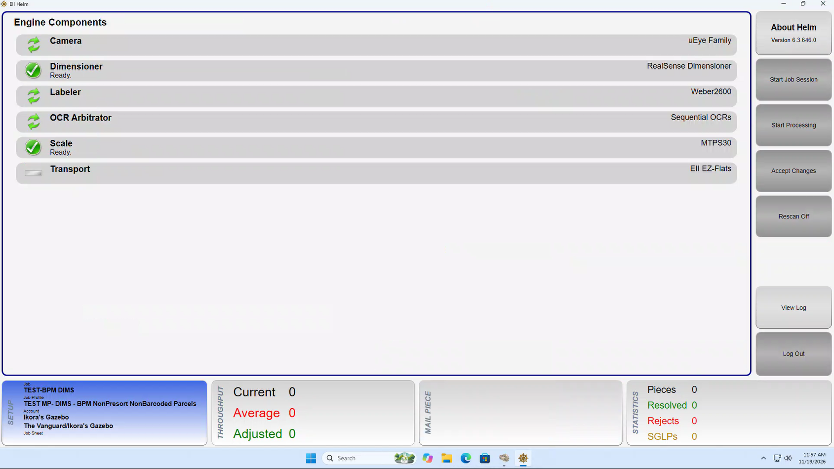
Select the account and department profiles the job will be run under.
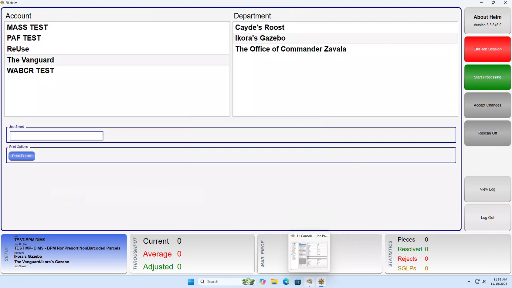
- Click on the green "Start Processing" button.
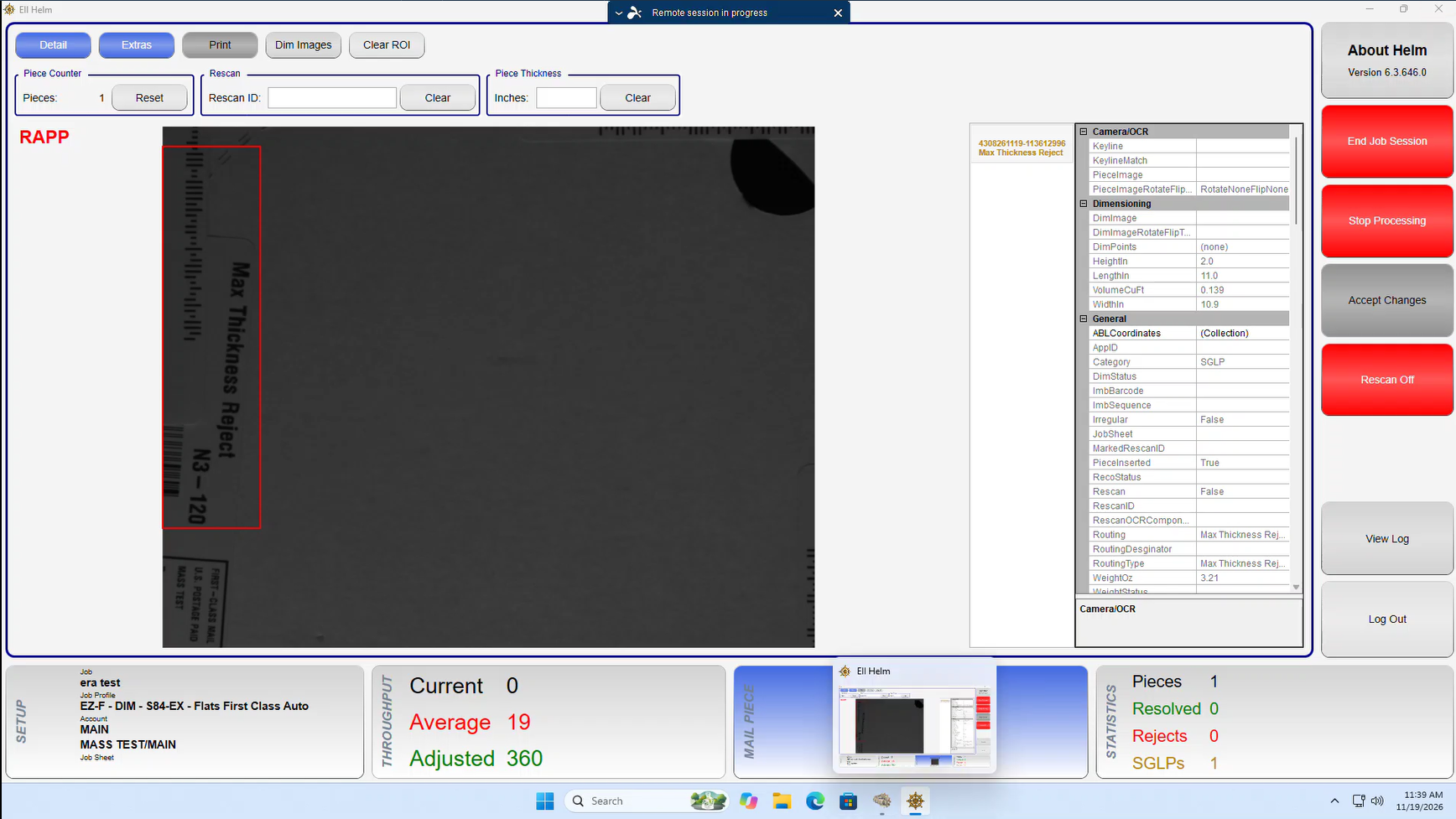
The operator will be directed to the Processing Page.
Process mail pieces as normal.
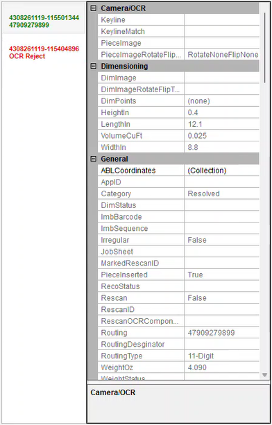
During processing, a pop-up will open in the image display section showcasing information collected on the mail piece. As more pieces are scanned, operators will be able to view information per mail piece.
Was this article helpful?
That’s Great!
Thank you for your feedback
Sorry! We couldn't be helpful
Thank you for your feedback
Feedback sent
We appreciate your effort and will try to fix the article